
Self-Leveling UAV Landing Platform
A Stabilized Landing System for Autonomous Drone Recovery on Moving Marine Vessels
Overview
Autonomous drones operating from marine vessels face a fundamental challenge: landing on a platform that is constantly moving due to waves and vessel motion. Even small pitch and roll disturbances can cause landing instability or failure.
This project explores a self-leveling landing platform designed to maintain a stable, horizontal surface for a UAV during recovery operations. The system uses inertial sensing, real-time sensor fusion, and servo-actuated mechanical stabilization to compensate for platform motion.
The project was originally developed in support of research related to the RobotX Maritime Challenge, where autonomous surface vessels deploy UAVs for reconnaissance and object retrieval tasks.
The final system demonstrates how embedded control systems and sensor fusion techniques can be applied to stabilize a landing surface in dynamic environments.
System Architecture
The platform operates as a closed-loop stabilization system consisting of sensing, estimation, and actuation layers.
IMU (Gyroscope + Accelerometer)
            ↓
      Sensor Fusion
   (Complementary Filter)
            ↓
      Orientation Estimate
            ↓
      Servo Control Logic
            ↓
   Self-Leveling Platform
Core Components
| Component | Role |
|---|---|
| Arduino Uno | Embedded control and signal processing |
| MPU-6050 IMU | Measures angular velocity and acceleration |
| MG995 High-Torque Servos (x2) | Platform stabilization actuation |
| Battery Power System | Dedicated power for control and servos |
| Mechanical Frame | Supports the landing platform and servo linkage |
The controller continuously reads orientation data from the IMU and commands the servos to counteract detected tilt.
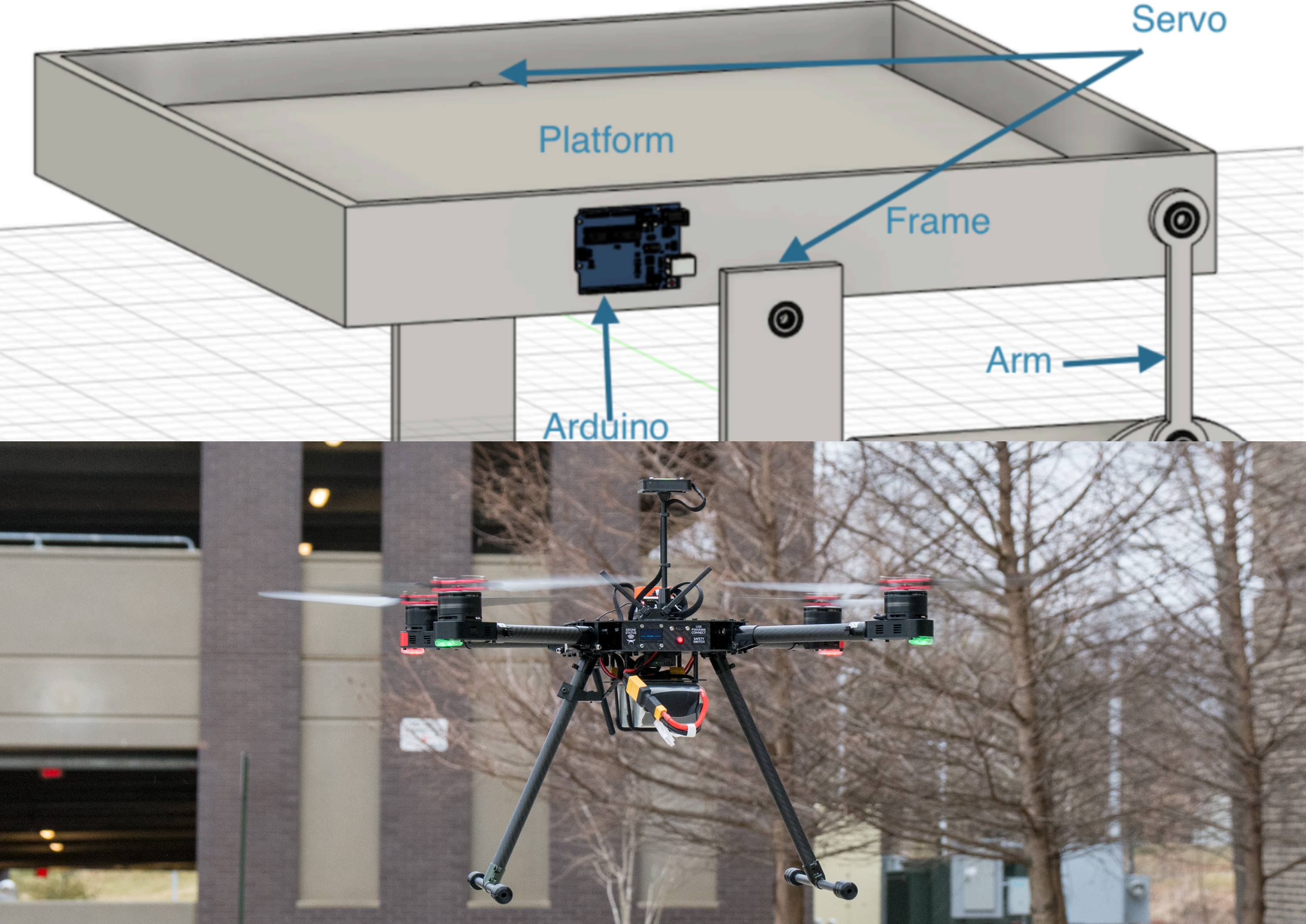
Mechanical Platform Design
The landing platform was designed as a servo-actuated stabilization mechanism mounted within a supporting frame.
Platform Characteristics
- Platform Size: 20 × 20 inches
- Actuation: Dual opposing servos
- Control Axis: Pitch compensation
- Construction: Foam board and lightweight structural frame
Two high-torque servos are mounted on opposing sides of the frame and connected to the platform through axles. By mirroring their motion, the system can rotate the platform to counteract external tilt.
Servo control equations:
servo1 = angle - 90
servo2 = 180 - (angle - 90)
This mirrored configuration allows the servos to maintain a level platform relative to gravity.
Inertial Sensing and Sensor Fusion
The system uses an MPU-6050 IMU, which provides:
- 3-axis accelerometer data
- 3-axis gyroscope data
Each sensor provides useful but imperfect measurements.
| Sensor | Strength | Weakness |
|---|---|---|
| Gyroscope | Accurate short-term angular velocity | Long-term drift |
| Accelerometer | Stable long-term orientation | Sensitive to noise and vibration |
To obtain a reliable orientation estimate, the system implements sensor fusion using a complementary filter.
Complementary Filter Implementation
The complementary filter combines both sensor signals:
- High-pass filter for gyroscope data
- Low-pass filter for accelerometer data
The resulting orientation estimate is computed as:
θ = A * (θ + gyro * dt) + B * accelerometer
Where:
| Parameter | Description |
|---|---|
| θ | Estimated platform angle |
| gyro | Angular velocity from gyroscope |
| accelerometer | Angle derived from accelerometer |
| dt | Time step between measurements |
| A, B | Filter weights |
Empirically tuned parameters:
A ≈ 0.926
B ≈ 0.07
This filtering approach provides a stable orientation estimate while remaining computationally lightweight enough for an Arduino-based embedded system.
Wave Motion Simulation
Testing stabilization performance on a real marine vessel was impractical. To simulate wave motion, a mechanical rocking system was designed and built.
Rocking Mechanism
The simulator consists of:
- Stepper motor (NEMA-17)
- Rotary wheel and arm mechanism
- Stepper motor driver
- Arduino control system
The rotary arm converts motor rotation into vertical displacement, producing a controlled oscillation of the platform.
Simulated Wave Periods
Three wave conditions were implemented:
| Mode | Oscillation Period |
|---|---|
| Mode 1 | 3 seconds |
| Mode 2 | 6 seconds |
| Mode 3 | 9 seconds |
The mechanism produced approximately 10 cm of displacement, representing realistic vessel pitch motion.
Stabilization Performance
Platform performance was evaluated by comparing:
- Uncontrolled platform motion
- Stabilized platform motion
Key performance requirements:
| Wave Period | Max Allowed Platform Motion |
|---|---|
| 3 s | ≤ 6 cm |
| 6 s | ≤ 4 cm |
| 9 s | ≤ 3 cm |
Experimental results showed that the stabilization system successfully reduced oscillation amplitude across all simulated wave conditions.
The controlled platform maintained significantly lower displacement compared to the uncontrolled baseline.
Early Vision-Based Landing Research
During early stages of the project, experiments were conducted using OpenCV and ArUco markers to provide positional awareness between the UAV and landing platform.
The goal was to estimate the relative pose of the drone to the landing pad using onboard camera input.
The approach leveraged OpenCV’s ArUco marker detection pipeline:
cv2.aruco.detectMarkers()
cv2.aruco.estimatePoseSingleMarkers()
This provides:
- 3D translation vector (tvec)
- 3D rotation vector (rvec)
From these values, the drone can determine:
- distance to landing pad
- relative orientation
- lateral alignment
This vision-based system was intended to guide autonomous landing maneuvers.
Project priorities later shifted toward solving the platform stabilization problem, which forms a critical subsystem for reliable UAV recovery.
Key Engineering Lessons
This project provided practical experience across multiple domains of robotics and embedded systems:
Embedded Systems
- Real-time sensor polling
- microcontroller control loops
- hardware interfacing
Robotics Control
- inertial sensing
- stabilization control
- servo actuation
Sensor Fusion
- complementary filtering
- IMU noise mitigation
- orientation estimation
Mechatronics
- mechanical design
- actuator integration
- system prototyping
Experimental Validation
- motion simulation
- performance testing
- system tuning
Future Work
Several extensions could further develop this system:
- Full 2-axis stabilization (pitch + roll)
- Integration with vision-based landing guidance
- Implementation on embedded Linux compute platforms
- Integration with autonomous UAV flight controllers
Combining the stabilized landing surface with vision-based localization would enable fully autonomous UAV recovery on moving marine vessels.